logo

rincian produk

Created with Pixso. Rumah Created with Pixso. Produk Created with Pixso.
gyro serat optik
Created with Pixso.

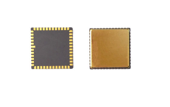
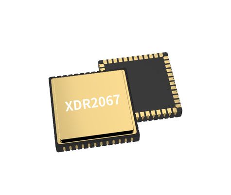
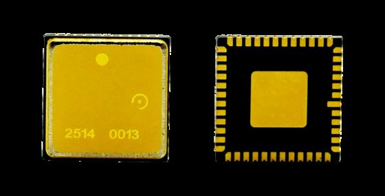
0.02°/h Bias Stability MEMS Gyroscope Chip for Inertial Measurement Unit

0.02°/h Bias Stability MEMS Gyroscope Chip for Inertial Measurement Unit

Nama merek: Firepower
Nomor Model: MGZ221HC
Moq: 1
harga: Dapat dinegosiasikan
Ketentuan Pembayaran: T/T
Kemampuan Penyediaan: 500/bulan
Informasi Rinci
Tempat asal:
CINA
Nama Produk:
PCB GYRO
Jangkauan:
400 derajat/dtk
Lebar pita:
>200Hz
Resolusi:
24 bit
Faktor skala:
16000 lb/derajat/dtk
Penundaan (disesuaikan):
<1,5 md
Ketidakstabilan Bias:
0,5 derajat/jam
Kemasan rincian:
spons + kotak
Menyediakan kemampuan:
500/bulan
Menyoroti:

0.02°/h MEMS gyroscope chip

,

MEMS gyroscope for inertial measurement

,

high stability fiber optic gyro

Deskripsi produk
0.02°/h Bias Stability MEMS Gyroscope Chip for Inertial Measurement Unit

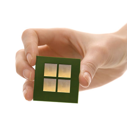
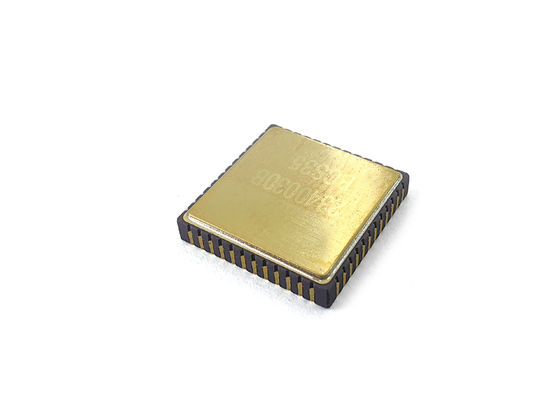
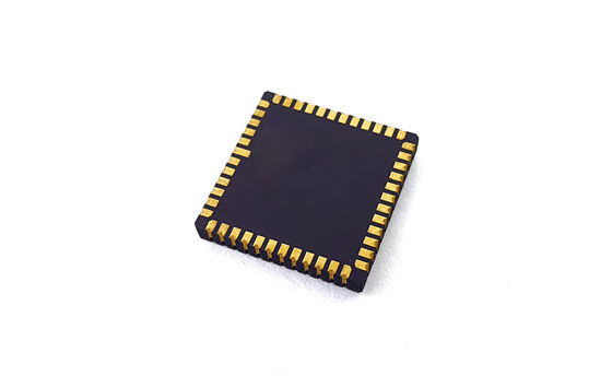
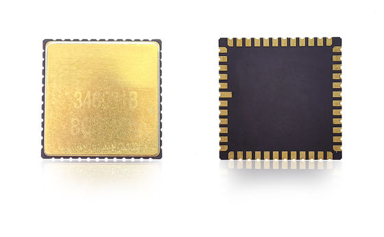
Our MEMS gyroscope chip delivers high-precision angular rate sensing for advanced inertial navigation and motion control applications. Designed with aerospace-level reliability and industrial-grade durability, it provides ultra-low noise, low bias instability, and excellent temperature stability for platforms that require long-term accuracy and robust performance.

Engineered for UAVs, autonomous robots, and industrial equipment, this MEMS gyro chip offers fast dynamic response, compact form factor, and low power consumption — making it ideal for embedded navigation systems and precision motion platforms.

PCB Design Guidelines
  • Decoupling capacitors for pins VCP, VREF, VBUF, and VREG should be placed as close to the pins as possible with minimized trace resistance
  • Other ends of decoupling capacitors for VREF, VBUF, and VREG should connect to nearest AVSS_LN and then to signal ground via a magnetic bead
  • Decoupling capacitors for VCC and VIO must be placed close to corresponding pins
  • VCC operation requires about 35mA current - use wide PCB traces for voltage stability
  • Avoid routing under the package for smooth assembly
  • Position components away from stress concentration areas, heat sources, and mechanical contact points
0.02°/h Bias Stability MEMS Gyroscope Chip for Inertial Measurement  Unit 0
Technical Specifications
Performance Unit MGZ332HC-P1 MGZ332HC-P5 MGZ318HC-A1 MGZ221HC-A4 MGZ330HC-O1 MGZ330HC-A1
Range deg/s 400 400 400 400 400 100
Band Width @3DB customized Hz 90 180 200 200 300 50
Output accuracy(digital SPI) bits 24 24 24 24 24 24
Output rate(ODR)(customized) Hz 12K 12K 12K 12K 12K 12K
Delay(customized) ms <3 <1.5 <1.5 <1.5 <1 <6
Bias stability deg/hr(1o) <0.05 <0.05 <0.1 <0.5 <0.1 <0.02
Bias stability (1σ 10s) deg/hr(1o) <0.5 <0.5 <1 <5 <1 <0.1
Bias stability (1σ 1s) deg/hr(1o) <1.5 <1.5 <3 <15 <3 <0.3
Bias error over temperature (1σ) deg/hr(1o) <5 <5 <10 <30 10 5
Bias temperature variations, calibrated(1σ) deg/hr(1o) <0.5 <0.5 <1 <10 <1 <0.5
Bias repeatability deg/hr(1o) <0.5 <0.5 <0.5 <3 <0.3 <0.1
Scale factor at 25°C lsb/deg/s 20000 20000 16000 16000 20000 80000
Scale factor repeatability (1σ) ppm(1o) <20ppm <20ppm <20ppm <20ppm <100ppm <100ppm
Scale factor vs temperature (1σ) ppm(1o) 100ppm 100ppm <100ppm <100ppm <300ppm <300ppm
Scale factor non-linearity (1σ) ppm 100ppm 100ppm <150ppm <150ppm <300ppm <300ppm
Angular random walk(ARW) °/√h <0.025 <0.025 <0.05 <0.25 <0.05 <0.005
Noise(Peak to Peak) deg/s <0.15 <0.3 <0.35 <0.4 <0.25 <0.015
GValue sensitivity °/hr/g <1 <1 <1 <3 <1 <1
Vibration rectification error(12gRMS,20-2000) °/hr/g(rms) <1 <1 <1 <3 <1 <1
Power-on time (valid data) s 750m
Sensor Resonant Frequency hz 10.5k-13.5K
Environmental Specifications
  • Impact (power on): 500g, 1ms
  • Impact resistance (power off): 10000g, 10ms
  • Vibration(power on): 18g rms (20Hz to 2kHz)
  • Working temperature: -40℃ to +85℃
  • Store temperature: -55℃ to +125℃
  • Supply voltage: 5±0.25V
  • Current consumption: 45ma
0.02°/h Bias Stability MEMS Gyroscope Chip for Inertial Measurement  Unit 1
Installation Guidelines

High-performance MEMS gyroscope is a high-precision test equipment. To achieve optimal design performance, consider these installation recommendations:

  • Evaluate sensor placement using thermal analysis, mechanical stress simulation (bending measurement/FEA), and impact robustness testing
  • Maintain appropriate distance from:
    • PCB thickness recommendations: 1.6-2.0mm to minimize inherent stress
    • Buttons/mechanical stress points
    • Heat sources (controllers, graphics chips) that may raise PCB temperature
  • Avoid placement in areas prone to mechanical stress, warping, or thermal expansion